
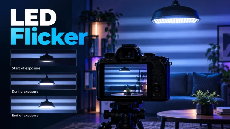
Why do LED lights flicker on camera when the room looks steady to your eyes? A camera records limited exposure windows, while some lights vary their output rapidly. Different windows can capture different amounts of light. With sequential sensor readout, different rows can also sample different parts of the light cycle, producing bands. The practical fix depends on the actual light, camera mode, exposure duration, and recording rate—not one universal shutter setting.
Start by separating a camera-visible pattern from a lamp that visibly behaves abnormally in the room. This guide covers safe recording tests and exposure sampling. It does not teach electrical repairs or determine whether a light is electrically safe. Stop using damaged equipment and consult a qualified person where a physical fault is suspected. No real lighting experiment or detector benchmark was performed for the conceptual examples below.
Describe the pattern before changing settings
Watch a recorded clip, not only the live preview. Does the entire image brighten and darken? Do horizontal strips move through a wall? Is the pattern confined to one display or fixture? Does it appear only after dimming, only in slow motion, or only in a downloaded copy? These observations give you a useful test question. “The LEDs flicker” is too broad to guide a controlled comparison.
Choose a non-sensitive scene with a steady camera position and a plain surface illuminated by the suspect source. A blank wall can make brightness changes easier to compare than a moving performer. Keep a static reference edge in view so you can distinguish illumination changes from movement. Do not stare into a bright source or aim a laser at the sensor; neither is needed for this review.
Make a small log with the recording mode, capture rate, exposure duration, fixture state, dimmer setting if visible, and what you saw. Record “unknown” for a light’s modulation frequency unless it is documented or properly measured. An app preview or a guessed band count is not a trustworthy frequency measurement. A source label saying “LED” does not describe its driver, dimming method, or behavior in this particular setup.
Keep the original files from each comparison and name the changed variable in your notes. Do not apply an enhancement or flicker-removal effect before deciding which capture conditions made the pattern appear. If the question concerns a received clip, obtain an earlier or better-quality copy if possible. The compression-artifact guide covers delivery defects that can complicate your observations.
Understand the two timing systems
Pulse-width modulation, or PWM, controls output by changing how long a source is on within repeated switching cycles. A camera’s exposure integrates light over its own limited duration. ENTTEC’s LED and camera timing explanation describes how those systems can interact to produce camera-visible pulsing or bands. Its pixel-product examples are not specifications for an unidentified household bulb.
The important distinction is between the light’s changing output and the camera’s sampling of it. A steady-looking room can still contain a source that changes within a short exposure. Conversely, visible flicker in the room is not something to dismiss as merely a camera problem. This article does not claim a universal threshold for what every person’s vision can perceive.
Mains-related variation and PWM are not identical explanations. A light’s power supply and driver can affect its output, while a dimming system may impose another pattern. Do not assume that a regional 50 or 60 hertz power supply reveals an LED’s actual modulation frequency. It can be relevant context without determining the waveform. Mixed fixtures in the same shot may need separate observation.
A useful first question is whether the problem follows one light or the whole room. If a small practical lamp shows bands but a neighboring light does not, separate their contributions where it is safe to do so using ordinary controls. If the camera changes exposure automatically, that may complicate the comparison. Label each change and avoid interpreting an uncontrolled sequence as a measurement of the lamp.
Work through a clearly hypothetical sampling example
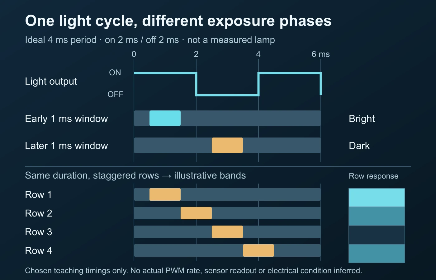
Imagine an idealized source with a four-millisecond repeating cycle. In this invented waveform, it is fully on for two milliseconds and off for two. That corresponds mathematically to 250 cycles per second. It is not a claimed frequency of your light or a product recommendation. The example isolates timing so that the mechanism is easier to follow.
Take a one-millisecond exposure starting halfway through an on interval. It captures light throughout that exposure. Move the same-duration window halfway into the off interval, and it captures none in this idealized model. The camera setting has not changed, but the phase of the light relative to the window has. That explains why a short exposure can be sensitive to where it lands.
Now extend the window to one complete four-millisecond period. For this perfectly repeating waveform, any such complete-period window includes two milliseconds of on time. Its starting phase no longer changes that total. This is a mathematical property of the chosen waveform, not a guarantee that a real fixture has a perfectly stable period or that a camera can achieve an exact matching exposure.
The example also shows why a nominal frame-rate match alone is not enough. Frame rate describes the spacing of sampling opportunities; exposure duration describes the length of each opportunity. A row can still integrate an awkward portion of a cycle. Write down both quantities. If the actual light waveform and sensor timing are unknown, use controlled observations rather than claiming that your camera and fixture are synchronized.
Use the diagram as an explanation, not a calculator for an unknown source. The bright and dark outcomes follow from the stated ideal on/off pattern. Real drivers, multiple emitters, changing dim levels, and exposure processing can be more complicated. Those complications are reasons to test the actual intended configuration, not reasons to invent a more precise-looking number.
Separate rolling bands from whole-frame pulsing
Sequential row exposure means one part of a sensor can observe a different time from another part. Baumer’s exposure-principles documentation explains this distinction. With changing illumination, row timing can matter even when the scene is not moving. That differs from the geometric bending of a moving object, although both involve capture timing.
For a recorded band pattern, note its orientation, where it appears, and whether its position changes across frames. Do not count strips and turn the result into a definitive driver frequency without knowing readout timing and the relevant sampling conditions. A useful description is “horizontal brightness bands cross the wall.” It is not “this proves the light pulses at a particular frequency.”
Whole-frame pulsing describes a broader brightness change across successive frames. It can raise a different comparison question from one localized strip. Look at a stable region under each light, and consider whether automatic exposure or scene changes were active. A global-looking pattern does not identify the camera’s shutter architecture. Describe the scope of the observation before assigning a mechanism.
This is an illumination troubleshooting task, not a full rolling-shutter distortion guide. A tilted pole during a pan and a dark strip across a stationary wall are different observations. Keep their notes separate so a later reviewer knows whether you were testing geometry, brightness, or both. If the actual authenticity claim is broader, the video forensics guide supplies the multi-evidence context.
Choose a camera-side test, not a universal fix
Consult the documentation for the recording mode you will actually use. Some controls operate only in still photography; others are available in specific video modes or firmware versions. Nikon’s Z9 high-frequency flicker-reduction update, for example, documents shutter fine-tuning with mode conditions. It does not establish that every camera offers the feature or that a generic anti-flicker menu corrects every LED pattern.
If you can set exposure manually, keep the camera position, frame rate, fixture setting, and composition fixed while comparing supported durations. Change one parameter at a time. Review the actual files at their intended playback speed and inspect the affected region. Record which settings reduced the observed problem and what other visible trade-offs appeared. Do not label a preview-only improvement a successful recording test.
Nikon’s Z5II video flicker-reduction guidance describes regional-frequency settings and example shutter choices for fluorescent or mercury-vapor lighting. That is a device-specific context, not proof that a 50/60 hertz setting matches an arbitrary PWM LED. Start with the correct manual and verify the result rather than applying a copied list blindly.
A longer exposure may change how much of the light cycle is integrated, but it also changes the treatment of motion. A duration that reduces bands on a static wall may smear a moving label you need to read. Evaluate both requirements in the same test. The best practical result is not always the cleanest wall; it is a usable recording of the subject at the intended rate.
If fine adjustment is supported, use it deliberately and document the implemented setting. Camera displays can round values, and some features have mode restrictions. Keep the source clip and the settings note together. If you cannot reproduce the successful state, you have a lead rather than a dependable shooting setup. A recorded comparison provides better practical evidence than confidence based on a familiar shutter fraction.
Change the lighting safely when camera settings are insufficient
Use ordinary, manufacturer-approved controls only. If a light’s dim level is relevant, compare a small number of permitted settings while keeping the camera fixed. Do not assume the effect of dimming is identical across products. Some fixtures or modes can behave differently at different levels. Write down what was changed and what the recorded files show.
If a venue permits it, remove the problematic source from the shot or substitute a suitable, documented recording light. A supplier’s claimed “flicker-free” label should be checked against the intended frame rate, exposure, and dimming conditions. Request the relevant specifications and make an actual capture comparison before relying on it for an important event. This is an operational check, not a shopping roundup.
Mixed illumination needs an isolation plan. A ceiling fixture, stage panel, decorative strip, and screen can contribute separate timing patterns. Do not keep adjusting the camera indefinitely when solving one source makes another worse. Where safe and authorized, compare them individually using their ordinary switches or controls. If a source cannot be isolated, document that limitation and consider changing the framing or recording arrangement.
Never open a lamp, modify its wiring, bypass a dimmer, or improvise a power supply to fix a camera pattern. No exposure setting repairs overheating, damage, or an electrical fault. If people can see unexpected pulsing or the equipment behaves abnormally, stop and consult the appropriate qualified support. This guide deliberately stops before electrical diagnosis or repair instructions.
Run a controlled scene review before the important recording
Consider a fictional interview setup with a practical lamp behind the subject. The room looks steady, but the recorded background shows moving dark bands. You have not measured the lamp and do not know its driver frequency. Your first useful step is a baseline clip with the normal interview framing, intended capture rate, and documented exposure. This is a planned exercise, not a test we performed.
| Comparison | Keep fixed | Record the result |
|---|---|---|
| Exposure duration | Fixture state, rate, framing, camera position | Band visibility and motion-detail trade-off |
| Supported fine adjustment | All other camera and lighting controls | Actual implemented value and recorded improvement |
| Fixture dim level | Camera configuration and composition | Which permitted state changes the pattern |
| Isolated light source | Subject, camera, and comparison region | Whether the problem follows that source |
| Intended slow motion | Documented lighting state and subject task | Usability at final playback speed |
Review the baseline and one exposure comparison first. If the band changes, you have identified a relationship worth testing—not necessarily its exact physical frequency. If it does not, move to a permitted fixture-state comparison rather than changing five settings at once. A note saying “the issue changed after adjusting exposure” is stronger than a guessed driver diagnosis.
Include the subject’s movement in the final validation. A clean static background can conceal the trade-off you will encounter when someone turns, gestures, or holds a product. Once you have a usable candidate setup, repeat the actual planned movement and inspect the original recording. If the result is inconsistent, retain the failing sample instead of selecting only the successful moment.
End the exercise with a practical decision: use the documented setup, replace or exclude the source, alter the shot, or report that acceptable recording was not achieved. No step requires proving that the light or camera is defective. The record should show what was tried, what remained fixed, and what changed, so another person can reproduce the decision rather than memorize a magic setting.
Recheck slow motion and the delivered copy
A configuration that works at ordinary speed may not work in a different high-rate recording mode. Capture timing and permitted exposure durations can change. ENTTEC’s technical guidance specifically treats slow-motion work as demanding for camera/light interaction; its product numbers are not a universal threshold. Test the intended mode itself rather than filming normally and assuming a slow-motion setting will behave identically.
Separate capture rate from playback rate in the log. A clip captured at a high rate and slowed for delivery is not the same test as an ordinary-rate clip slowed by editing. Keep the original and the intended output so you can locate when an observed pattern became noticeable. If you use processing to reduce a pattern, label the output as processed rather than treating it as untouched evidence.
Check the recipient’s actual downloaded file, not only a small embedded preview. Record whether the issue exists in the source, the export, or both. If a delivery copy adds unrelated blockiness or timing problems, keep those findings separate from illumination sampling. The metadata guide can help describe the current file without inventing the settings of its original recording.
Check whether the pattern belongs to the file or the display
If only one viewing screen seems to pulse, do not immediately assign that behavior to the captured lighting. Compare the same downloaded source on another suitable display when available, without screen-recording either playback. Inspect the same segment and note the player, viewing conditions, and any processing you intentionally changed. This is an isolation step, not a claim that every playback system can be treated as a calibrated instrument.
A pattern that can be located in decoded frames is a different observation from discomfort or pulsing noticed only during one live playback. Keep those findings separate in your report. If you cannot safely make the distinction, describe the limitation and stop; extended exposure to uncomfortable visual patterns is not required to troubleshoot a recording. No health conclusion follows from this comparison.
When handing the material to someone else, supply the unchanged source and the segment of concern, not a phone video of your monitor. Explain whether the issue appeared in the recording, its preview, or one playback arrangement. That simple distinction can prevent a second reviewer from investigating the wrong timing system.
Do not turn a flicker observation into an AI verdict
The timing model gives an ordinary explanation that deserves consideration. It does not prove that the video is authentic, and it does not prove that every brightness anomaly came from an LED. A synthetic or edited clip can also contain a light pattern. The question is what the available source, capture conditions, and comparison files support in this specific case.
Use narrow language: “the recorded bands changed with the documented exposure setting,” “the pattern follows the practical lamp,” or “the source configuration is unknown.” Those statements preserve the difference between an observation and a cause. Do not label a stranger’s clip fake because a wall has bands, or call it verified because a plausible camera mechanism exists.
If a claim still matters after capture conditions are considered, investigate that claim separately. The fake-video verification guide distinguishes editing, staging, synthesis, and false context. Flicker troubleshooting helps prevent one visual misunderstanding; it does not replace source verification or technical media analysis.
Questions about camera-visible LED flicker
Why does a light look steady but flicker in video?
Limited camera exposure windows can sample a changing light output differently. Sequential row timing can also turn illumination changes into bands. This does not identify the actual modulation frequency.
Does the local power frequency tell me an LED’s PWM rate?
No. Regional power frequency is useful context, but driver design and dimming can produce different output timing. Do not assume every LED uses the same waveform or frequency.
Will an anti-flicker setting solve every LED problem?
No. Features have camera, mode, and light-specific limitations. Check the appropriate documentation and review an actual recorded comparison.
Should I change shutter speed or frame rate first?
Keep your intended recording task in mind and isolate one supported change at a time. Exposure comparisons are useful when rate must remain fixed, but they can change motion blur. There is no universal sequence that fits every device.
Can I repair the light to remove camera bands?
This guide provides no electrical repair instructions. Use approved controls, change the recording arrangement, or seek qualified support. Do not open, rewire, or bypass safety features.
Do moving bands prove a video is AI-generated?
No. Ordinary camera/light interaction can produce them. Investigate consequential authenticity claims with source and technical evidence rather than one visual pattern.
Sources and example limits
- ENTTEC: Why Do LEDs Flicker on Camera? PWM, Shutter Speed, and How to Fix It — camera/light timing; manufacturer examples remain product-specific.
- Baumer: Rolling shutter, global shutter — two principles of exposure — sequential row timing, not an unknown camera’s measured readout.
- Nikon Z9: New Menu Item, High-Frequency Flicker Reduction — supported fine-tuning and mode conditions.
- Nikon Z5II: Video flicker reduction — device-specific regional-frequency guidance and limits.
Sources checked on 14 October 2026. The waveform and interview worksheet are original conceptual teaching examples, not a lamp or camera experiment. No product frequency, universal fix, electrical safety finding, or detection accuracy is inferred.
Flicker alone is not an AI verdict.
Check the source video and consider how it was recorded.